Tips for using iSqFt Takeoff
How to: Easily perform a takeoff from a project in iSqFt 10
Did you know you can easily do a takeoff from a project in iSqFt 10?
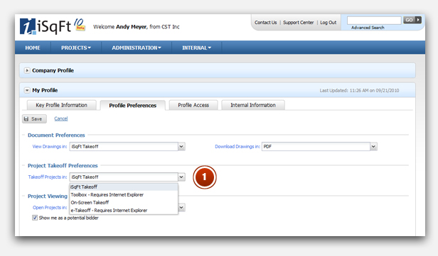
1. Make sure your takeoff preference is set to iSqFt Takeoff in iSqFt 10 — this can be checked under the Administration menu > My Profile > Profile Preferences
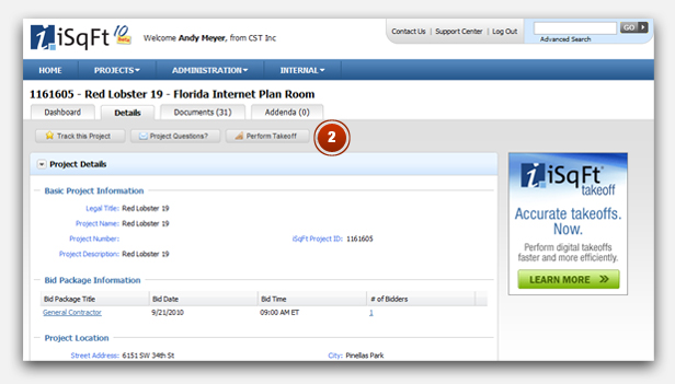
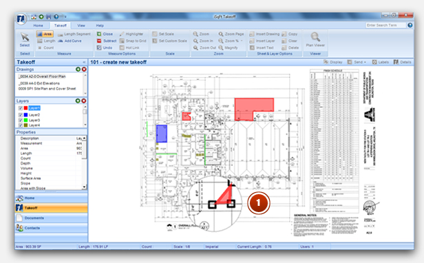
2. Find a project you want to work on in iSqFt 10. Then click on the Perform Takeoff button
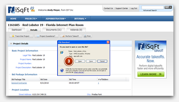
3. Click Open in the File Download window
Note: The time it takes for iSqFt Takeoff to open could vary depending on your computer hardware specifications. Please refer to the Systems Requirement sheet for recommended specifications to run software.
Trick: To speed up the iSqFt Takeoff launch process, have the software already opened prior to clicking on the Perform Takeoff button.
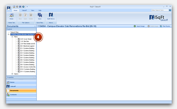
4. iSqFt Takeoff will automatically launch. Then click on either the "+" for Plans or Specs in the Explorer panel to open the designated file branch
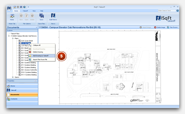
5. Double click on a drawing or spec to download the file and make it viewable. Then right click on your mouse and choose "Add Drawing to Takeoff" function
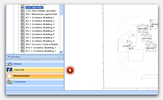
6. Click on the Takeoff tab located on the lower left side of the iSqFt Takeoff interface
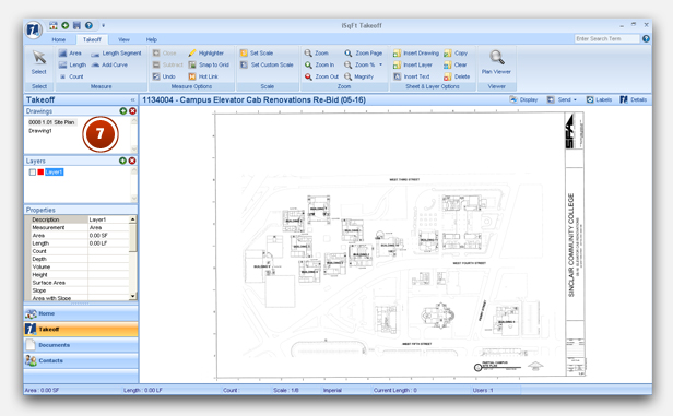
7. You will see the drawing or spec you added from Step 5 listed in the Drawings panel as well as in the viewer. You're ready to do your takeoff
How to: Use the Plan Viewer feature to view another drawing or spec page quickly
Did you know you can view another drawing or spec page using the Plan Viewer feature or set up a Hot Link to quickly reference another drawing or document later?
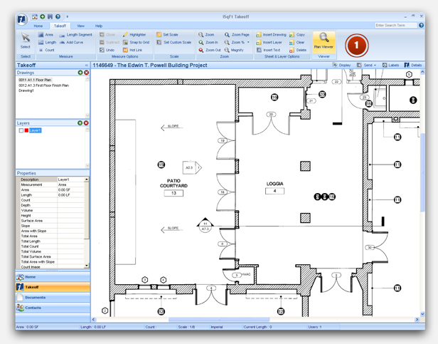
1. To view a second drawing or spec page, click on the Plan Viewer button
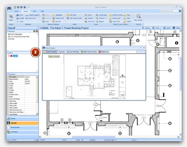
2. Click on Import Drawing and choose the drawing or document you want to view, then you can zoom and move around in it
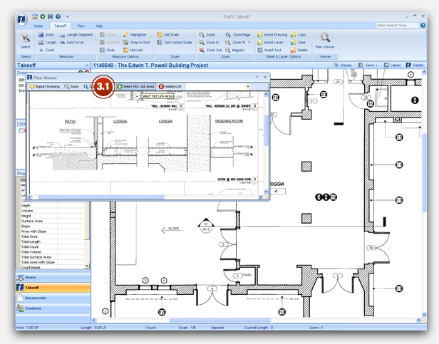
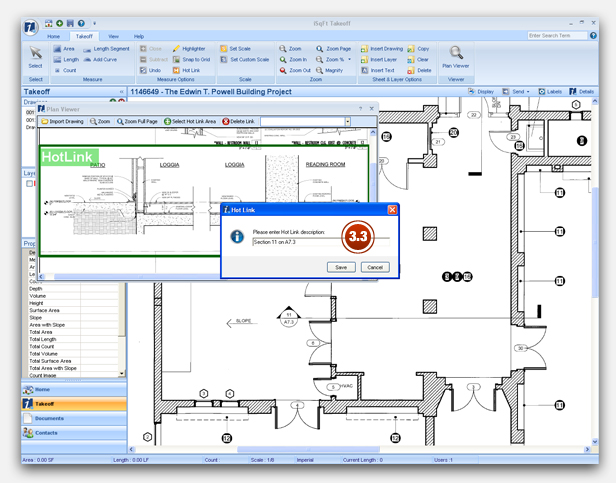
3. If there is a specific part of the drawing or document you want to review later, click on Select Hotlink Area in the Plan Viewer window, draw a box around the information you want to come back to, type in a Hot Link description and click Save
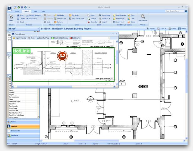
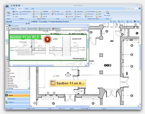
4. Click on Hot Link and place the [H] symbol on the drawing
![Click on Hot Link and place the [H] symbol on the drawing](images/2_takeoff_hotlink_btn.jpg)
![Click on Hot Link and place the [H] symbol on the drawing](images/2_takeoff_hotlink_add.jpg)
5. To view your Hot Link area, just double click on the Hot Link icon you placed on the drawing in Step 4.2. Your Hot Link will launch in the Plan Viewer window
How to: Clear a user from a project
What should I do when I get a message saying my takeoff project is currently opened by another user when it is not the case?
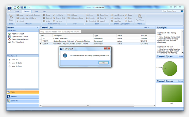
Steps to clear user from the project:
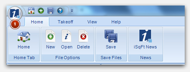
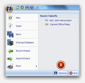
1. Open the maintenance menu by clicking on the iSqFt icon located in the upper left corner
2. Click on the options button
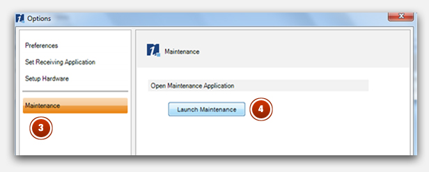
3. Click on Maintenance
4. Launch Maintenance
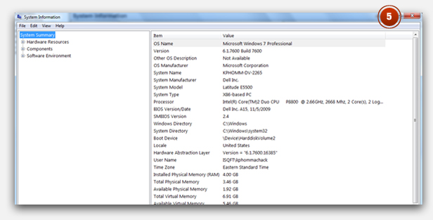
5. Close out of the System Information window
6. Click on Takeoff Status located in the left panel of the Maintenance window. You will see the project(s) that is being in use. Click on the project(s) and then the Clear User From Takeoff button to free up the project
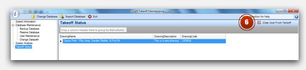
Return to the Project List in iSqFt Takeoff and open the project that was just cleared in Maintenance. The project is now available to be worked on.
How to: Add a grid to an area takeoff
Adding a grid to an area takeoff
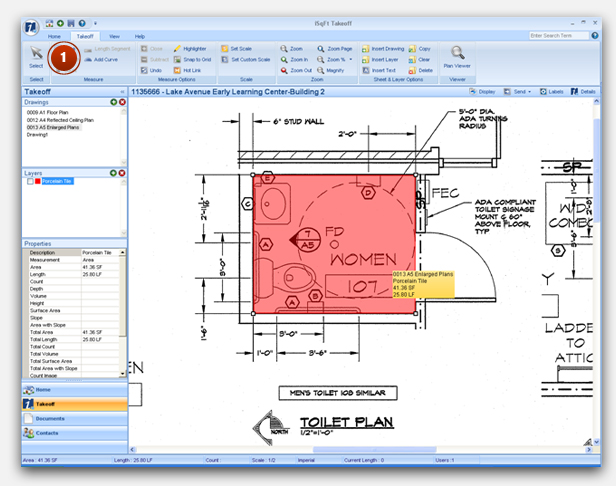
1. Select the area to add a grid by clicking on the Select button near the iSqFt icon at the top left corner. Then click on the highlighted area where the grid will be added.
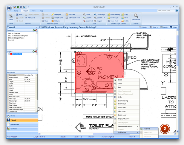
2. Right click on the mouse, then go to Grid Options and click on Add Grid
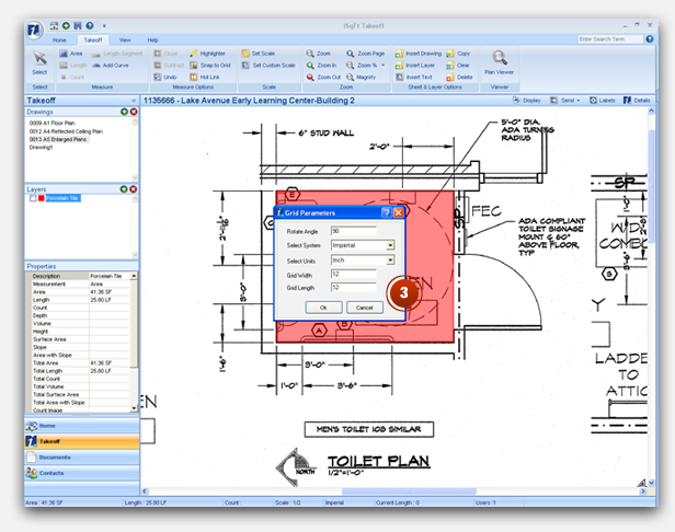
3. Set the angle, system of measurement, units and grid size. Then click Ok.
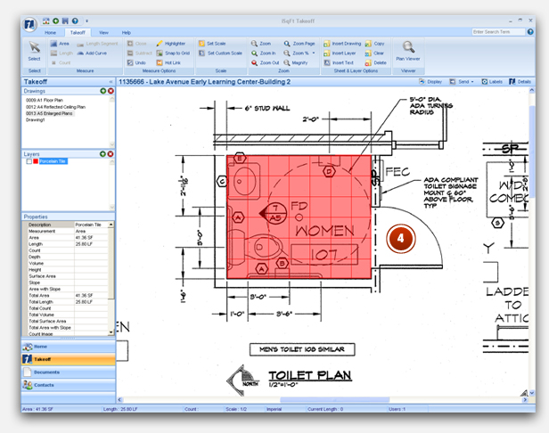
4. The Grid is added to the area takeoff
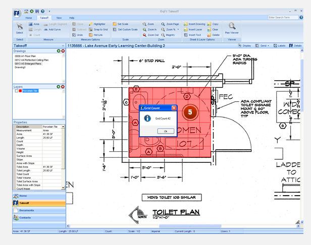
5. To get the number of tiles:
- click on the area with the Grid
- right click on the mouse
- go to Grid Options
- click on Grid Count
How to: Use various magnify/zoom features
Use the MagniPoint technology to get a closer look at the drawing while doing a takeoff.
1. While in takeoff mode, press the "Ctrl" button on your keyboard and a circular scope will appear. Move the scope around with your mouse and click on points of interest to do your takeoff.
2. To zoom into a particular section of the drawing, select the Zoom buttom on the ribbon and drag the cursor on the area you wish to zoom in.
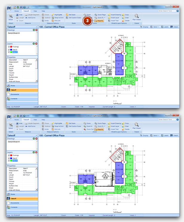
3. Use the Magnify tool for quick access to close-up view of certain sections of the takeoff/drawing
With the drawing in the zoom page mode, click on Magnify and hold down on the left mouse button to move the rectangular scope around the drawing.
How to: Use the overlay feature to see differences between two drawings
How to use the overlay feature to see differences between two drawings (original vs. addendum) on top of one another:
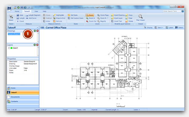
1. Go into your takeoff project, then click on the drawing in the Drawings panel that you would like to overlay on top. In this example, it's the drawing titled Sample Blueprint.
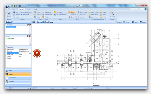
2. Navigate to the Properties panel. Click in the Overlay Image text box and an icon with three dots (...) will pop up. Move your cursor on it and click it.
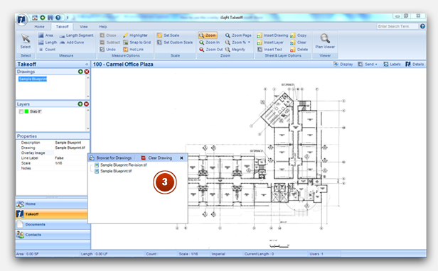
3. A window will appear on your screen allowing you choose a file you would like to overlay on top of the selected drawing. In this example, we will select the file titled, Sample Blueprint Revision.
Note: Documents associated to the takeoff project are displayed in the window. You also have the flexibility to browse for other files on your computer.
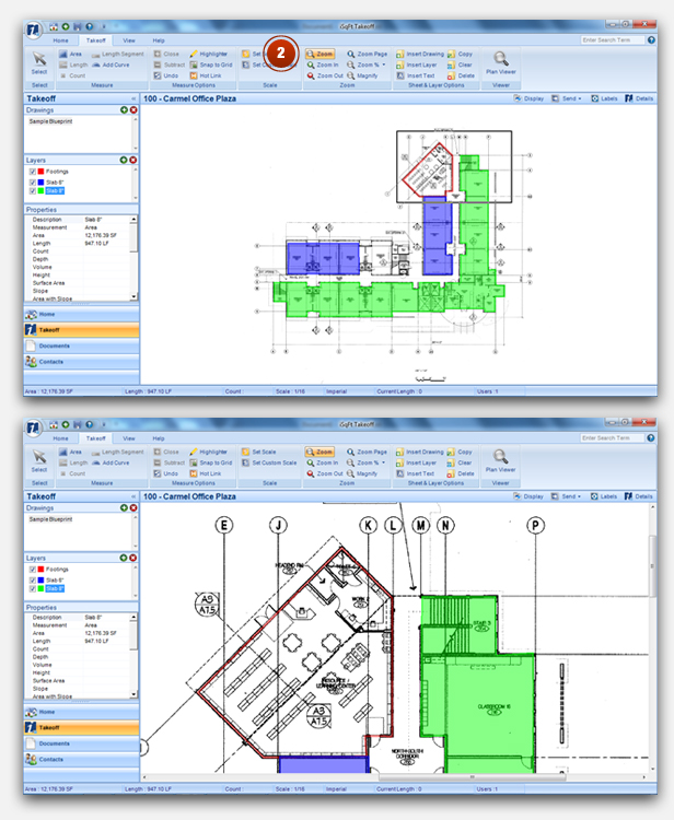
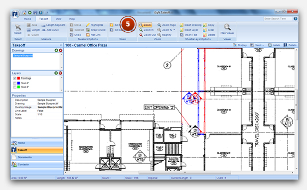
4. Once a file has been selected, it will automatically be overlaid on top of the original drawing. In the Properties panel, the empty field adjacent to the Overlay Image text is now populated with the name of the selected overlay file (Sample Blueprint Revision). The difference between the two drawings is identified by the red line (original drawing) and blue line (overlay drawing). No changes are represented by the black line.
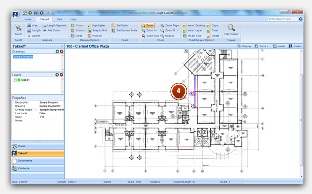
5. Use the Zoom feature to get a closer look at the changes between the original and revised drawings. For this example, the revised drawing has two changes that are different from the original drawing.
How to: Insert a layer on a takeoff project
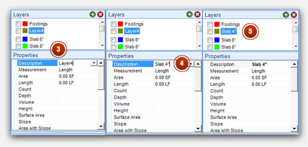
How to quickly insert a layer and create a name for it:
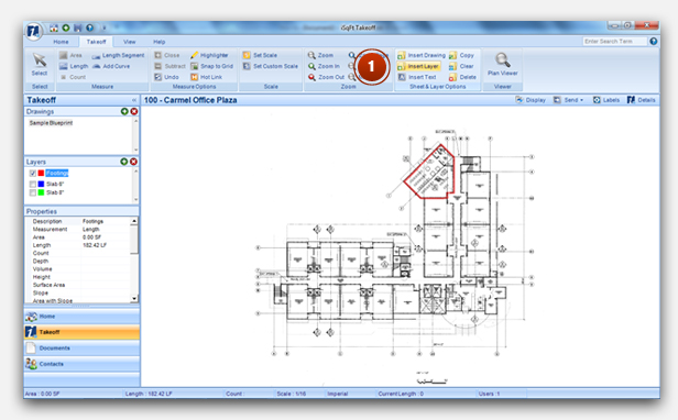
1. In the takeoff project, click the Insert Layer on the Takeoff ribbon. A new layer called Layer 4 will appear in the Layers panel. In this example, it shows up under the Footings layer because that was selected as the place to insert the new layer.
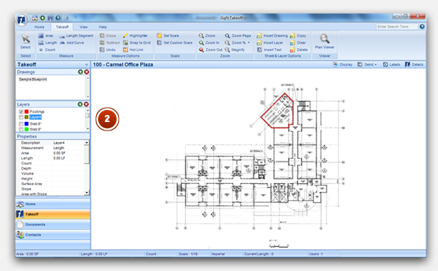
2. Navigate to the Properties panel, click on the Layer4 text. Then delete it and write in a new name for the layer. Press "Enter" to make the change happened.