Walkthrough
Toolbox2 Walkthrough
The following steps will walk through the steps to complete a sample take off using Toolbox2.
Creating a Project
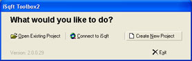
When you first start Toolbox2 you will be presented with three options like the image below. Select Create New Project to open a blank project file.
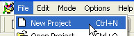
If you already have Toolbox2 open you can create a new blank project file by going to File > New Project or by using the keyboard shortcut <Ctrl+N>.
Click on New Project and the following box displays:
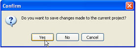
Click Yes if you've done a takeoff on another project and want to save the changes you've just made. If you do not want to save the changes, click No. This will bring up a blank white page and allow you to import plans from a new project
Adding Plans From Your Computer
(Note: iSqFt Toolbox2 is compatible with
200, 300, and 400 dpi files in tiff and cpc format.)
To add a drawing from a location on your hard drive into iSqFt Toolbox2,
you will need to do the following:
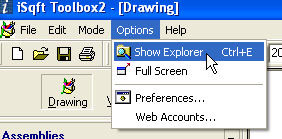
Ensure the Project Explorer is displayed. If it is not displayed you can open it by going to Options > Show Explorer (Hotkey: <Ctrl+E>)
Under the Project Explorer go to the
Documents section.
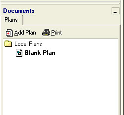
Click the Add Plan button.
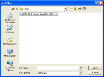
Navigate to where you have the plans saved on your hard drive. Double
click one drawing to add it. To select multiple drawings, left click
your first drawing and then hold the Shift key on the keyboard
and left click on the last
drawing to add them in. By default, plans from iSqFt will be located in
an iSqFt Downloads folder on your desktop.
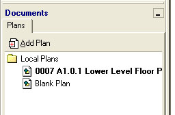
Your drawing(s) will now be added to the Documents list and will display
in the main viewing pane.
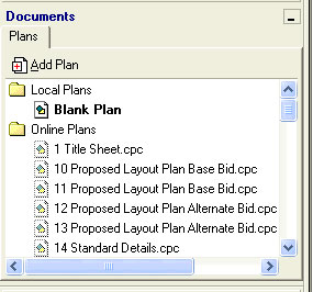
Adding Plans From The iSqFt Website
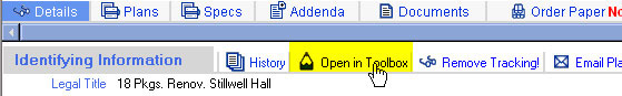
On the Details page of projects on the web site you will find an Open
in
Toolbox button. When you add a project into iSqFt Toolbox2 using the
'Open in Toolbox'
button the site will automatically add that project into your Project Tracking
folder, making it easier to locate on the site later. You can reach the
Open in Toolbox by either using the Web Icon in iSqFt
Toolbox2, or by logging in normally through Internet Explorer.
This will move the drawings to the Plans tab in iSqFt Toolbox2.
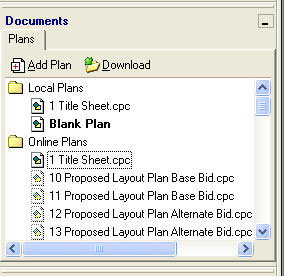
To download the plan into iSqFt Toolbox2, double click the drawing name
under the Online Plans folder. This will move the drawing to your
Local
Plans folder.
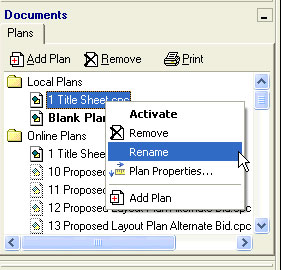
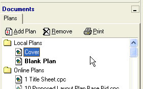
The drawings can be renamed from the Local Plans folder, but not the
Online Plans folder. To rename a drawing, Left-click to select the
drawing to be renamed and then right-click it and choose "Rename" from
the menu. Type a new name and press "Enter" on the keyboard.
(*Note: If no Internet Connection is available when opening a project,
the Online Plans folder will not display.)
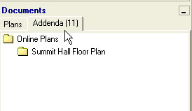
Adding Addenda Plans
Clicking the Open in Toolbox button on the isqft website will also add any applicable addenda
drawings - but NOT the specifications or DJVU documents. Any Addenda
documents will display on an Addenda tab in iSqFt Toolbox2.
Setting the Scale
To set the scale for a plan, zoom in on the plan until you can locate the scale. Then, at the bottom of your screen, click on No Scale or by using the toolbar shortcut.
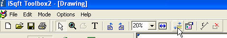
This will display the Properties
box.
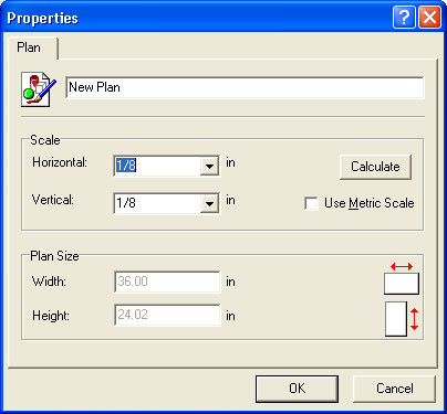
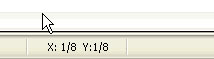
You can then enter your scale on the line marked Horizontal. This will also add it to the line marked Vertical. Then, click OK at the bottom. You should now notice that it reads X: Y: with your scale next to those letters.
If you want to set the scale in metric, you can check the Use Metric Scale box.
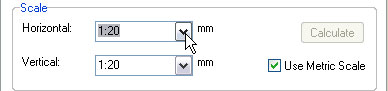
The values tab will always be consistent with the scale that is displayed at the bottom.
Using Assemblies
This walkthrough will assume that you have already created the assemblies you plan on using for your takeoff. To learn more about creating and editing assemblies, refer to the iSqFt Toolbox2 Help file by selecting Help > Contents (Keyboard shortcut <F1>) from inside the Toolbox2 program.
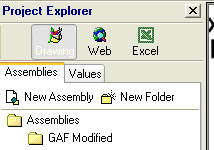
Ensure the Project Explorer is displayed. If it is not displayed you can open it by going to Options > Show Explorer (Hotkey: <Ctrl+E>).
Click on the Drawing icon below Project Explorer and be sure the Assemblies tab is selected.
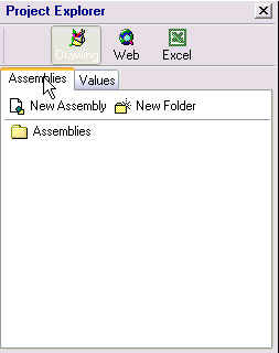
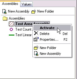
Click the Assemblies folder to display its contents. Navigate to the Assembly you would like to use to measure with and either Double-Click, or Left-Click to select and Right-Click on the Assembly and choose "Activate" from the list.
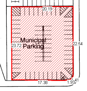
Square Footage
Takeoff
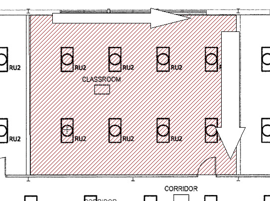
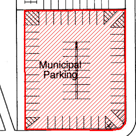
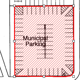
Move your cursor over to the Drawing pane. You will notice the cursor
has changed to a crosshair to more accurately select your points. Find
the first corner of what you will measure and left-click and release.
Continue clicking the corners and follow in a clockwise or
counter-clockwise order until the whole area is hatched. Hit "Enter" on
the keyboard when you have entered the last point to complete the
figure.
There are advanced features for editing your area by right-clicking it and selecting "Figure Properties".
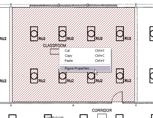
From figure properties you can set a pitch for a roof, set a depth for a volume, enable or disable dimensions or subtract the current figure from the values.

Displaying Values
Single Plan Values
After using an assembly to do a takeoff, you should have figures on the
the plans for the areas you have marked up.
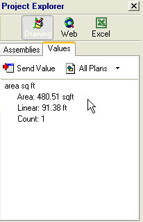
Click on the Values tab below the Project Explorer.
The value of your takeoff now appears. In this example, an area assembly was used to get the square foot of a parking lot. Also, notice that by using an area assembly, the linear foot value is calculated.
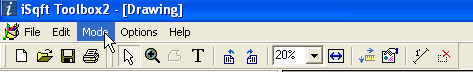
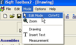
You can also display the linear foot values directly on the plan. (Note: It is not possible to display area values on the plan.) After you draw your takeoff, click on Mode at the top of iSqFt Toolbox2.
Then, click on Edit Mode.
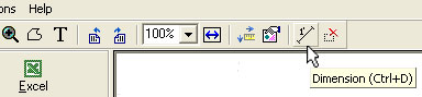
Click on the takeoff you just drew on the plan. White squares should appear around the corners.
Next, click on the Dimension button on the toolbar at the top (or use the keyboard shortcut <Ctrl+D>). The linear foot values will appear on the takeoff.
Values of All Plans
To find the values of all the plans you have completed a takeoff on,
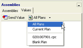
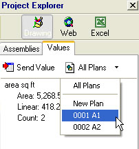
click on the All Plans button under the Values tab.
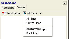
On the drop down box, select All Plans. The cumulative values for all the plans you have done takeoffs on will now appear. In this example, the combined values for plans A1 and A2 are now shown.
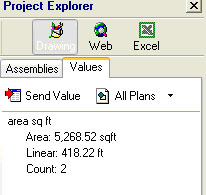
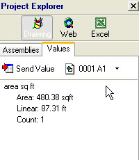
You can always go back to display the values of a single plan by clicking on the All Plans button and selecting the plan you wish to see.
In this example, the values for plan A1 are now shown.
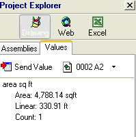
And then the value for plan A2 can also be displayed.
Transferring Values to Excel
Once you have the values of your takeoff, you can transfer these values into an Excel spreadsheet. To do this, click the Excel button under Project Explorer.
![]()
A new Excel document will appear. You will still have your Project Explorer to the left with your Assemblies and Values.
![]()
Next, highlight the cell you wish to put the value in, and then double click on the value under the Values tab.
![]()
The value will then be inserted into the highlighted cell.
![]()
![]()
![]()